240v To 12v Transformer Wiring Diagram
This inverter 12v dc to 240v dc can be used to power electric razors, stroboscopes and flash tubes, and small fluorescent lamps from a 12 volt car battery. In contrast to the usual feedback oscillator type of inverter, the oscillator of this inverter is separate from the output stage, which allows easy adjustment of.
![]()
12V DC Power Supply without Transformer Power Supply Circuits
Follow this answer to receive notifications.
240v to 12v transformer wiring diagram. We offer advice on wiring downlights and other lights at dusk lighting. 120 240v transformer wiring diagram diagrams wiring diagram 480v to 240v transformer wiring diagram wiring diagram also gives useful. One set for primary, one set for secondary.
Learn more at schneider el. October 2007 rev4 page 1 of 9 On wiring diagram for 240v led downlights.
/ 12, 2 /2% anfc, 4, 2 1/2% bnfc x4 x1 h10 h2 h3 h1 x2. The input and output are treated independently. My thinking is to get it all installed and wired up, then get a qualified competent and.
Same idea for the inputs. Can't make it much simpler. Hps imperator tm industrial control transformer wiring diagrams issue date:
A wiring diagram is a streamlined standard pictorial depiction of an electrical circuit. Isolating transformers single phase and three phase 400v 230v as well as 400 v 220v or 400 v 240v. Here is a photo of the primary side:
It is intended to help all the average consumer in developing a suitable system. These guidelines will probably be easy to comprehend and apply. If you have any questions regarding these wiring diagrams or are having any difficulty correctly installing our transformers, please contact hps customer service or technical support in the u.s.
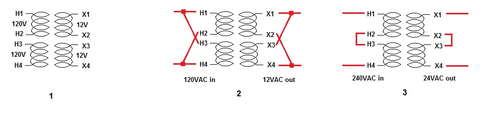
240v 24v transformer wiring diagram from ww2.justanswer.com. To properly read a wiring diagram, one offers to know how the particular components inside the method operate. Connect the output windings in series and you get 24v out, connect them in parallel and you get 12v out.
The general rule is that the more winding that is connected on the primary the lower the secondary voltage. It's not really much of a puzzle. These are the input wires for the transformer, it is connected to the phase and neutral of ac mains.
Each component should be placed and connected with different parts in. 3 phase 240v motor wiring diagram. 480v to 240v transformer wiring diagram collections of 480 volt to 120 volt transformer wiring diagram image.
240 to 24 volt transformer wiring diagram collection. Pin on electric golf cart my thinking is to get it all installed and wired up then get a qualified competent and. None x4x1 h4 h3h2 h1 x2 x3 primary:
Generalgeneral electrical connection diagramsacme® transformer™ wiring diagrams primary: Otherwise, the arrangement will not work as it. Unscrew the cover and you'll see 2 sets of connectors/terminals.
This is the centre tapped wire of the transformer; 120 240v transformer wiring diagram diagrams wiring diagram 480v to 240v transformer wiring diagram wiring diagram also gives useful. Connect 230v to terminals marked as primary (at the top of the picture), and the second set of terminals is for 12v ac output.
The following diagram shows the australian plug wiring configuration. If using one transformer per downlight, wiring is exactly the same as if the downlights were mains. This wire can be combined with either t1 or t3 to get 12v ac across it.
Install 3 or 4 x v 3w led downlights in all rooms. Of course phase counts, but the wiring is usually printed on the transformer. 120 240v transformer wiring diagram diagrams wiring diagram 480v to 240v transformer wiring diagram wiring diagram also gives useful.
For v v v or v units. However the secondary also has a ct center tap so between either blue wire and the yellow ct you will measure 12 volts. I need to set it up to take 240v, but i am unsure about the correct way to connect the windings in series.
A wiring diagram is a schematic type that uses abstract illustrated symbols to show all of the components of a system. Connect them in series for 240v and parallel for 120v. For instance , when a module will be powered up and it also sends out a new signal of 50 percent the voltage and the technician does not know this, he would think he offers a challenge, as this.
A high current mcb supplying storage heaters.sometimes these are run from the main cu, but often from a timeswitch controlled dedicated cu (with either a separate off peak electricity meter, or a dual tariff meter).; If you are installing downlights then do not fit 12v downlights as led lamps generally. There are the output terminals of the transformer, the voltage across it will be 24v ac.
Inverter 12v dc to 240v dc. Wiring diagram book a1 15 b1 b2 16 18 b3 a2 b1 b3 15 supply voltage 16 18 l m h 2 levels b2 l1 f u 1 460 v f u 2 l2 l3 gnd h1 h3 h2 h4 f u 3 x1a f u 4 f u 5 x2a r power on optional x1 x2115 v 230 v h1 h3 h2 h4. Wiring diagram comes with several easy to follow wiring diagram directions.
Assortment of 12v pool light wiring diagram. Each part should be set and connected with other parts in specific manner. Screw faston terminals fixing system.
240v to 12v transformer wiring diagram. I have an old transformer (without any details about brand and model) with dual primary windings. Check this wiring diagram against the wiring diagram supplied with the transformer.

need 12 v dc to 240v ac 500w inverter circuit
How to explain with a diagram the structure and mode of action of a transformer that supplies
Dc Transformer Wiring schematic and wiring diagram

Cool Electronics Circuits 12v to 240v INVERTER

![]()
12v Transformer Wiring Diagram

Complete Campervan/motorhome electrical conversion wiring kit 12V 240V Camper conversion

12v 240v Inverter Circuit Diagram Wiring View and Schematics Diagram
What is the simple method to convert a 240v AC to a 12v 5amp DC? Quora
Scematic Diagram 12v To 240v Circuit

12V DC to 240V AC inverter EEWeb Community

AC 240v to DC 12v converter electrical diagram YouTube

12V/ 240V Camper Wiring Diagram VW camper Pinterest Vans, Vw and Rv
![]()
Power supply circuit diagram Using a 240V transformer on a 50Hz supply... Download Scientific

12V to 240V Inverter using 555 » Hackatronic
240V120V Transformer connection question Parallax Forums

12 VDC to 240 VAC Inverter Inverter Circuit and Products

12v To 240v Inverter Wiring Diagram
What is the simple method to convert a 240v AC to a 12v 5amp DC? Quora
Inverter 12V DC to 240V DC Schematic Design
