Siemens Vfd Wiring Diagram
Move sto switch to on position and wire sto signals according to operating instructions. Check connections of l1, l2, l3;

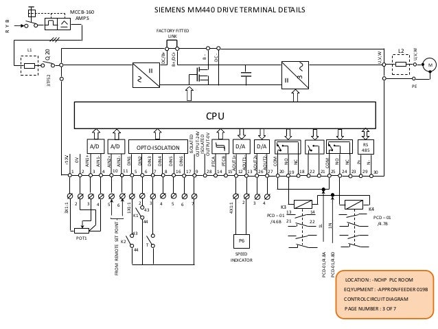
Siemens Micromaster 440 Wiring Diagram Wiring Diagram And Schematic Diagram Images
Positioning, processing, moving and machining.

Siemens vfd wiring diagram. For a detailed drawing see figure 5: If products and components from other manufacturers are used, these must be recommended or approved by siemens. Learn the basic wiring of variable frequency drives / vfd with our electrician steve quist.
Motors should be connected up according to the circuit. Siemens standard drives division manufacture standard inverters up to 90kw for this purpose. A vsd high performance inverter for general purpose applications available in various voltage ranges and power.
Application note ap0400076en vfd wiring best practices effective july 2014 2 eaton corporation www.eaton.com control wiring similar consideration need to be taken when looking at the control wiring. Siemens vfd wiring diagram by facybulka posted on april 15, 2019 warning siemens products may only be used for the applications described in the catalog and in the relevant technical documentation. We strongly recommend using a certified electrician.
They are ideally suited for use in situations where fast. The vfds showed in the video are the d720s (230v single phase) and the d720 (230v three phase). Siemens motor control center wiring diagrams are at your fingertips within seconds.
A vfd drive controls the motor speed. Sinamics g120c inverter 6 compact operating instructions, 07/2015, fw v4.7 sp3, a5e36391768b aa 1 fundamental safety instructions 1.1 general safety instructions warning risk of death if the safety instructions and remaining risks are not carefully observed Connect the vfd to supply power [r/l1, s/l2, t/l3] using the recommended protected circuit.
It shows the elements of the circuit as simplified shapes, as well as the power as well as signal connections between the devices. Climatix vfd wiring, see figure 4: If vfd sends +24 v as the plc di card uses m of the same source it will be on, else if rfb is low, it reads at plc as 0 v and di will be off
The current product range consists of four different product types: Connect the motor to the vfd [u, v, w]. Install the inverter on a metal mounting plate in a control cabinet.
The mounting plate has to be unpainted and with a good electrical conductivity. Siemens products may only be used for the applications described in the catalog and in the relevant technical documentation. Vfd main circuit and control wiring diagram.
If vfd is sending run feed back signal to plc, do from vfd to di of plc plc will send +24 v signal to vfd dry contact and only one +24 v source returns back to plc, depending on the status of rfb. Available in to 335 hp this modular and scalable standard drive may be configured in a wide variety of designs to meet many industrial drive applications. Vfd is a short form of variable frequency drive or variable voltage variable frequency drive.the vfds are working based on changing the input frequency and input voltage of the motor, we can change.
Siemens handbooks are printed on chlorine free paper that has been produced from managed sustainable forests. If products and components from other manufacturers are used, these must be recommended or approved by siemens. Siemens standard drives product range.
Vfd start stop wiring diagram: Proper use of siemens products note the following: V20 inverter has not been designed to work with a residual current device.
The sinamics g inverter has been designed for. Warning siemens products may only be used for the applications described in the catalog and in the relevant technical documentation. Proper transport, storage, installation, assembly, commissioning, operation and
Variable frequency drives are used in the industrial landscape for the following applications, for example: Starting from very low power ratings to control washing machine drums up to medium power ratings for pumps used in municipal water supplies. (1) the vfd's three phase ac input terminals (r/l1, s/l2, t/l3) the power line's input terminals connect to 3 phase ac power through line protection or leakage protection breaker, it does not need to consider the connection of phase sequence.
Connect the vfd to the climatix rtu solution as follows: 200 v converter second environment, c2 no emc category In this video, we used the very popular mitsubishi d700 series vfd, showing single phase and three phase wiring instructions.
Operation, and maintenance of sinamics v20 inverters. Sinamics v20 inverter operating instructions, 09/, a5e page 46 2 x ferrites of type seiwa e04srm or equivalent in the vicinity of the motor terminals. Sinamics v20 getting started manual.
How to read a plc wiring diagram basic electrical design of panel simatic siemens pdf program electromechanical control panels vfd skills hands for motor pump general purpose interface module s7 standards and 200 2018 iec european directives access schematic. Here is a picture gallery about sinamics g wiring diagram complete with the description of. The vfd main circuit terminals shown as below figure.
The vfds showed in the video are the d720s (230v single phase) and the d720 (230v three phase). I am here with giving you a vfd start stop wiring diagram for running a vfd through panel board push button and keypad of the vfd (it is called hmi).
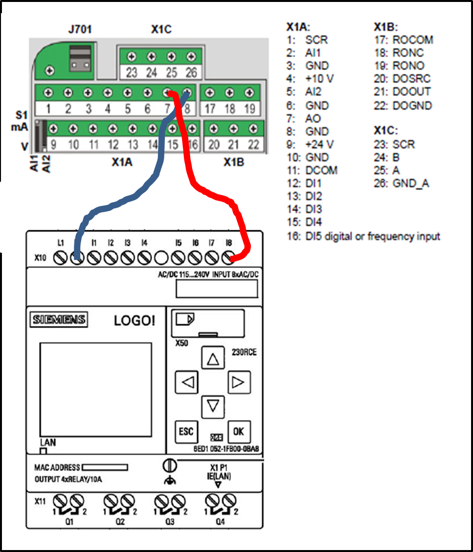
VFD Analog output to LOGO! Siemens

Pin en siemens drives wiring connection مهندس محمدیان 09132211861
Wiring Diagram For Vfd
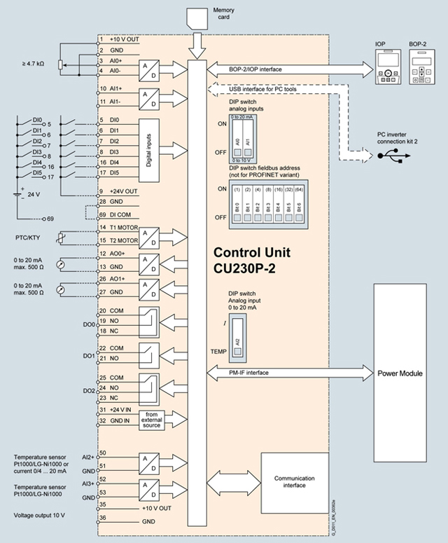
Siemens G120c Wiring Diagram Wiring Diagram

21 Best Abb Vfd Wiring Diagram Pdf

Pin on Electrics

[BW_0063] Vfd Wiring Diagram Further Siemens Profibus Connector Wiring Diagram Wiring Diagram
Siemen Micromaster 440 Control Wiring Diagram Complete Wiring Schemas

Delta Plc Wiring Diagram
Siemen Micromaster 440 Control Wiring Diagram Complete Wiring Schemas


Sinamics G120 Wiring Diagram Wiring Diagram And Schematic Diagram Images
Siemen Micromaster 440 Control Wiring Diagram Complete Wiring Schemas

siemens g120 wiring diagram Wiring Diagram and Schematic

Sinamics G120 Wiring Diagram Wiring Diagram And Schematic Diagram Images
Siemens Shunt Trip Breaker Wiring Diagram Gallery Wiring Diagram Sample

VFD control wiring diagram । Engineers CommonRoom YouTube

[BW_0063] Vfd Wiring Diagram Further Siemens Profibus Connector Wiring Diagram Wiring Diagram

Siemens Plc Wiring Diagram

[BW_0063] Vfd Wiring Diagram Further Siemens Profibus Connector Wiring Diagram Wiring Diagram