3 Phase Rcd Wiring Diagram
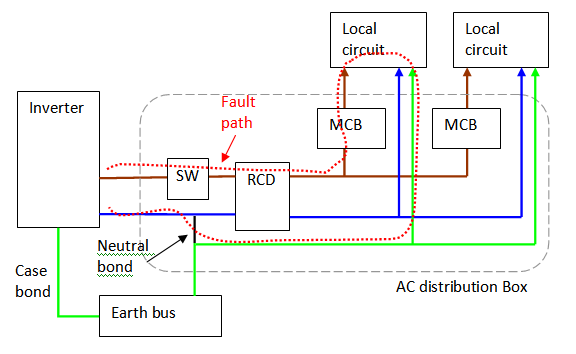
Pathetic diagram shows a 3 phase rcd unit. This compares the combined phase currents and compares the sum of them to the neutral current.

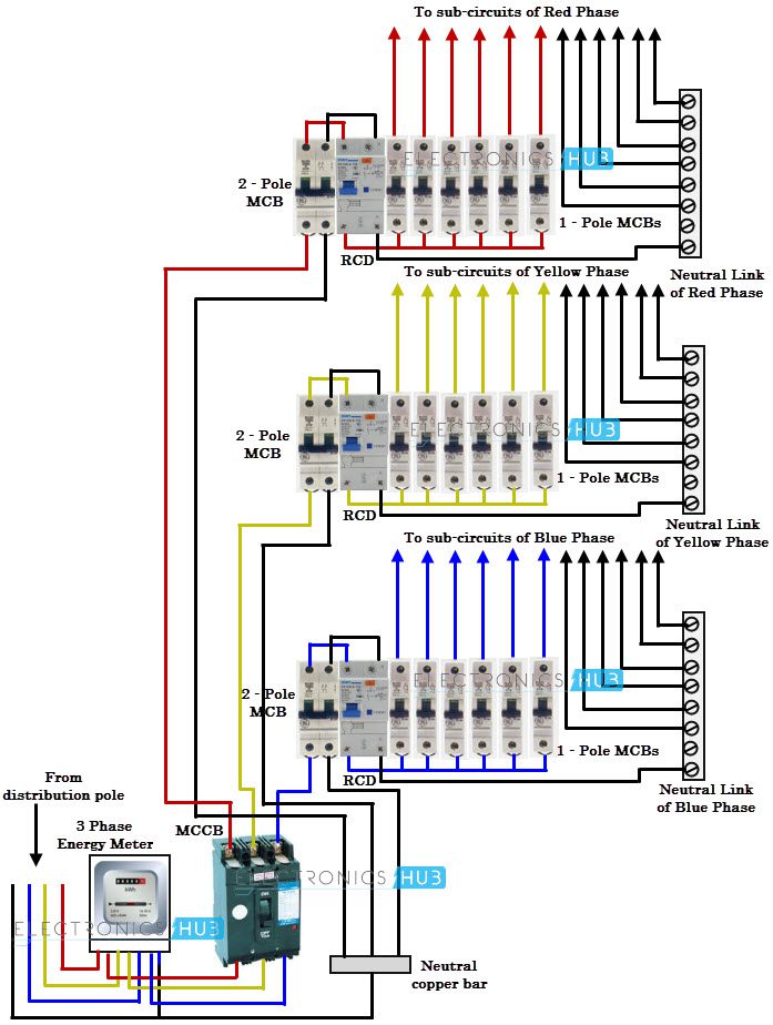
3 phase wiring installation in multi story building or house with kWh, MCCB, MCB, RCD, voltmeter
Adding a resistor across terminals 4/3 and 8/7/n, as shown.
3 phase rcd wiring diagram. Rcbo wiring has both active and neutral so that it can detect leakage current. 18 3 phase electrical switchboard wiring diagram electrical wiring electrical panel wiring house wiring. Clipsal 3 phase rcd wiring diagram.
In the case of a rcd with a phase to phase test circuit, there are no special requirements and the test function will operate with a three wire connection. If there is no neutral at all the rcd will be connected normally but a bridging resistor will need to be added. 3 phase distribution board wiring diagram pdf home electrical wiring basic electrical wiring distribution board.
Contactor 3 phase wiring diagram. The practical way of wiring the three phase 60a distribution board with a. There will be a circuit diagram on the rcd which will show the trip circuit configuration.
3 phase wiring installation in multi story building or house with kwh mccb mcb rcd voltmeter ammeter earthing system with comp installation wire building. How to wire rcd (residual current device) ? The rated voltage in such networks is 220 v.
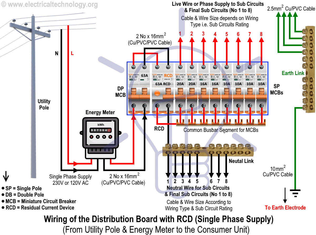
Rcds with a phase to neutral test circuit will require the connection of a resistor between the load side neutral terminal and a load side. One line diagram of simple contactor circuit. The following typical layout wiring diagram shows three phase distribution board and consumer unit installation in a residential/commercial area.
Demand of these three circuits must not exceed rating of rcd) ol n n n a neutral link do not earth ol clipsal rcd 2 4n 1 3n a mains switch a e n n an. Air conditioner contactor wiring diagram inspirationa wiring diagram. Clipsal rcd mcb wiring diagram schemas.
The detailed internal wiring for the sample db mcbs rcd units home electrical wiring distribution board diy electrical. In the above diagram, the alternator is connected to the load by three phase four wire system. Starting a three phase motor.
Should it be necessary to use a 4 pole rcd for a single phase circuit, poles 3 / 4 and n must be used, with a link between poles 5 / 6 and n (1.5mm² wire), otherwise the test device will not be energised when the test button is pressed and will not function. 6 when using a 4 pole rcd on a three phase 3 wire system, the n pole should not be used. Patent us20120230846 systems and methods of controlling pressure for fire pump wiring diagram electrical diagram electrical circuit diagram motorcycle wiring.
These two lines (line and. Can a 3 phase overload be wired for use with single motor starter. Three phase electrical wiring installation in home nec iec electrical wiring electrical panel wiring house wiring.
Out of balance current will not trip the rcd unless there is a fault to earth. 3 phase electrical switchboard wiring diagram and wiring of the distribution board with rcd single phas distribution board electricity basic electrical wiring. Clipsal rc and 4rc series residual current device wiring diagrams 1 2 main switch single phase e 3n 4n clipsal rcbm 4rcbm and 4rcbe series combined mcbrcd wiring diagram a warning combined max.
Three phase voltage is 415v if i take. A wiring diagram is a simplified traditional pictorial depiction of an electric circuit. Wiring diagram rcd consumer unit new wiring diagram for consumer unit book diagram schema electrical wiring basic electrical wiring diy electrical clipsal rc and 4rc series residual current device wiring diagrams 1 2 main switch single phase e 3n 4n clipsal rcbm 4rcbm and 4rcbe series combined mcbrcd wiring diagram a warning combined max.
Clipsal rc and 4rc series residual current device wiring diagrams 1 2 main switch single phase e 3n 4n clipsal rcbm, 4rcbm and 4rcbe series combined mcb/rcd wiring diagram a warning (combined max. The absence of a neutral line creates an issue where the test button would be supplied by the full concatenate voltage (typically ~400v), which could damage the circuit. The above image diagram is just an example and rcd is available in many shapes and.
3 phase distribution board wiring diagram pdf wiring diagram is a simplified tolerable pictorial representation of an electrical circuit it shows the components of the circuit as simplified shapes and the aptitude and signal contacts amongst the devices. If there is no neutral at all, the rcd will be connected normally but a bridging resistor will need to be added. You can use a 4 pole rcd but you need to look at the wiring diagram on the side to see whether the test button is connected to two of the phases or between a phase and neutral, in the latter if there is no neutral present then a resistor (value depending on the test button circuit) connected between one of the phases and neutral terminal will ensure the test button works,.
In brief, your diagram looks ok to me. In this single phase home supply wiring diagram, the main supply (single phase live (red wire) and neutral (black wire) comes from the secondary of the transformer (3 phase 4 wire (star) system) to the single phase energy meter (note that single phase supply is 230v ac and 120v ac in us). Schematic wiring diagram of three phase distribution board.

3 Phase Distribution Board Wiring Diagram Pdf Home electrical wiring, Basic electrical wiring
Clipsal 3 Phase Rcd Wiring Diagram Wiring Diagram
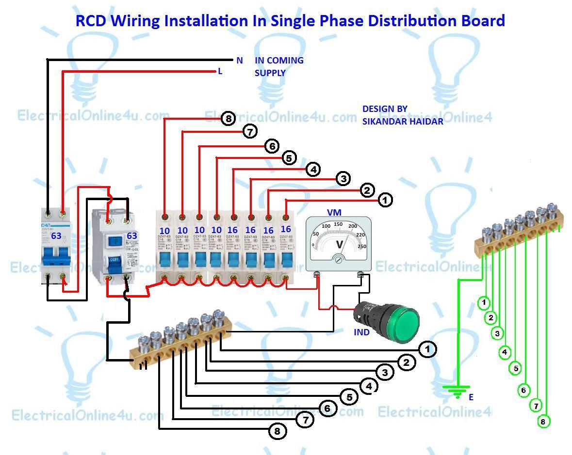
RCD Wiring Installation In Single Phase Distribution Board
What to do isolate or regenerate


3 Phase Rcbo Wiring Diagram yazminahmed

3 Phase Mcb Wiring Diagram Wiring Of The Distribution Board With Rcd Single Phase Home Supply

3 Phase Wiring Diagram Australia TINNINGSTREE

How To Wire A 4 Pole RCD Circuit Breaker For 3 Phase 4 Wire System

Three phase electrical wiring system for home & multifloor building

Clipsal 3 Phase Rcd Wiring Diagram Wiring Diagram
Clipsal 3 Phase Rcd Wiring Diagram Wiring Diagram


Clipsal 3 Phase Rcd Wiring Diagram Wiring Diagram
Three Phase Wiring

RCCB working function,three phase rccb,4 pole rccb working function,4 pole elcb working function
Fully Adjustable 800A 3 Phase RCBO with Metal Enclosure Protek UK

Elektronik & Messtechnik Three 3 Phase consumer unit,distribution board 4 pole RCD or isolation
Clipsal Rcd Wiring Diagram 5
3 Phase Wiring Diagram Australia TINNINGSTREE

Clipsal 3 Phase Rcd Wiring Diagram Wiring Diagram
