120v Coil Relay Wiring Diagram
Dpdt relay wiring diagram how to build a relay driver circuit types of relays relay terminals relay wiring diagrams This is the diagram below to learn all the pin terminals of a double pole double throw (dpdt) relay:
Wiring Diagram For 120v Coil Contactor Complete Wiring Schemas

Place the relay's rated coil voltage on these terminals.

120v coil relay wiring diagram. [/quote connected other lead to white neutral wire on the blower motor and its still closing the relay. Orange red blue blue black t1 l1 l1 l2 l3 l2 l3 x2 t2 t3 to 208/230v supply coil 3421 3 to stp (see diagram g) note: Relay can be the best option to control electrical devices automatically.
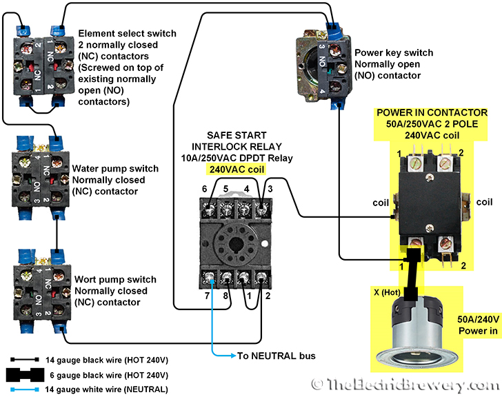
Pin's 8 & 6 as normally open pin's 8 & 5 as normally closed. This tiny and fully enclosed relay can switch a whole 15amp ac outlet worth of power with only 0.02 amps of coil current. When a relays coil is energized, current flow through the coil creates a magnetic field.
I can't seem to find a wiring diagram for your wood furnace so proceed with caution. The red led and the dc fan now shut off and the green led and the dc motor now turn on and operate. When ordering per case, enter the total number of pieces in the quantity field.
The following diagram shows how the above relay may be wired with a load, such that when the coil is energized, the load gets triggered or switched on through its n/o contacts, and through the attached supply voltage. But, it doesn’t mean link between the cables. It all rides on circuit that’s being built.
Coil above is wired for 230 v to. When the relay receives 12 volts of power, the relay snaps from the nc position to the no position. It can be used for various switching.
The coil 0.187 and the switch contacts 0.250. All connections are male spade connectors: The polarity of the voltage does not matter.
Din rail mount socket comes with two horseshoe clips. You need to take this wire and connect it to a neutral wire going to the fan motor: The magnetic coil attracts a ferrous plate, which is part of the armature.
The diagram above is the 5 pin relay wiring diagram. Do not use unless you plan to insert pullover wire spring. Dpdt relay omron my2n 240vac 24vdv my2 dc24 s automation and ly1n relays 50pcs ly2nj datasheet ly2n j 24vdc my2nj 24v power ขาย how to wire a d2 gs my4h us 11 pin spdt dc pinout of ly2 diy home 12dc 12v coil non circuit diagrams safety components 2nf 10a g7l 1a t.
So when wiring up these relays, the coil wire's will connect to pins 2 & 7 on the socket. This supply voltage in series with the load may be as per the load specifications. Whether in a dc unit where the polarity is fixed, or in an ac unit where the polarity changes 120 times per second, the basic function remains the same:
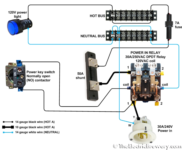
5.0 out of 5 starsbig performance in a small package. (remove red wire connecting x2 to l2). When the coil is energized by 120 power, it closes the contacts for the 240 volt power to pass from one side of the contactor to the other.
Model # mk2kpac120 unspsc # 39121515 catalog group # h7975. Pin's 1 & 3 as normally open pin's 1 & 4 as normally closed. Omron general purpose relay 24v dc coil volts 10a 120v ac contact rating 2w930 ly2 dc24 grainger.
As stated previous, the lines at a ice cube relay wiring diagram represents wires. This tutorial will show you the basic operation and wiring to base for 8 pin 24vdc and 240v ac relays See my switch terminology page for more on contact arrangements if you need to.
For example, if one case has 30 pieces and you. Injunction of 2 wires is usually indicated by. Occasionally, the wires will cross.
5 pin is compromised of 3 main. Merely ignore the control wiring in red 3ph starter/3ph motor/ reversible Latching relay, 120v ac coil volts, 10a @ 240.
The relay may be energized across a wide voltage range from 9vdc to 40vdc, making it ideal for 12vdc and 24vdc eol circuits. Reviewed in the united states on august 10, 2019. Electrically held relays — typical wiring diagrams contacts contact arrangement and markings open type relay rail mount open type din rail mount n.o.
24 vac/dc, 120 vac relays: How to wire relay terminals. General purpose relay, 120v ac coil volts, 10.
The 2 coil terminals is where the voltage is placed in order to energize the coil. Relays contain a red led which indicates when the relay coil is energized. Rewire red wires at coil.
There are different kinds of relays for different purposes. Model # 5x841 unspsc # 39121515 catalog group # h7982. The 19.3 ma operating current is constant across the operating range.
Coil above is wired for 230 v to pump motor, 120 v from isotrol or dispenser switch.

I have a 120V duct booster fan, a 24V thermostat, a 6AZT9 relay (from Grainger), and a 24V zone

Wiring Diagram Fir A Starter Cintrolling A 480v Motor With 120v Start/stop Button

120 Volt Relay Wiring Diagram / Ribu1c Rib Relays / To show you how to wire the relay, let's
20+ Latest 120v 2 Pole Contactor Wiring Diagram Stephan Fuchs

Wiring Diagram For 120v Coil Contactor Complete Wiring Schemas
20+ Latest 120v 2 Pole Contactor Wiring Diagram Stephan Fuchs

Wiring Diagram For 120v Coil Contactor Complete Wiring Schemas


240v Contactor 120v Coil Wiring Diagram Wiring Diagram and Schematic
Wiring Manual PDF 120vac Wiring

Wiring Diagram For 120v Coil Contactor Complete Wiring Schemas

How to build a control panel (part 1) Page 3 Home Brew Forums
HVACQuick How To's Wiring Generic 120V coil relay from
Wiring Diagram For 120v Coil Contactor Complete Wiring Schemas
Wiring Diagram For 120v Coil Contactor Complete Wiring Schemas

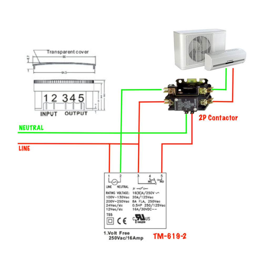
2 Pole Contactor Wiring Cool Wiring Diagrams
39 Timer Relay 120v Wiring Diagram Wiring Niche Ideas

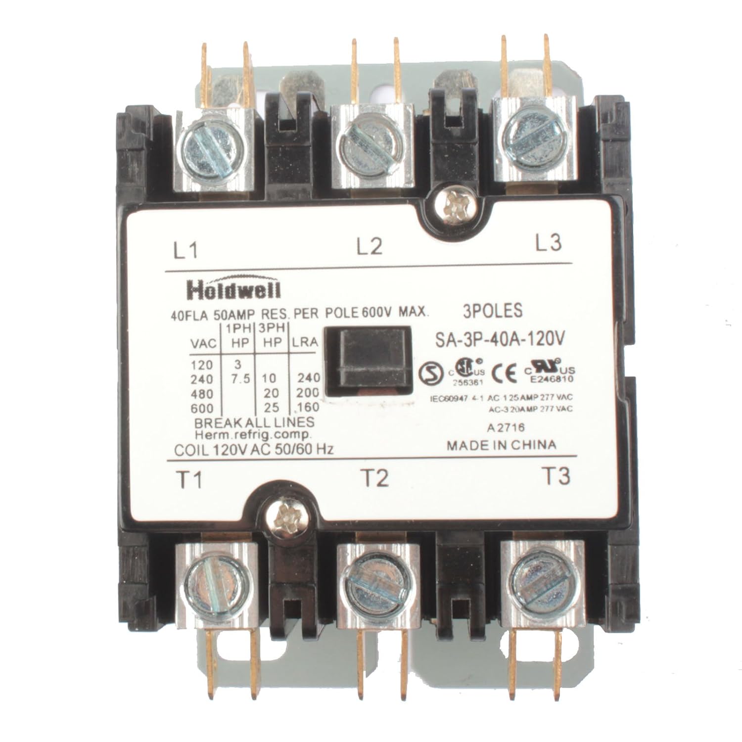
54 3 Pole Contactor 120v Coil Wiring Diagram Wiring Diagram Plan
Wiring Diagram For 120v Coil Contactor Complete Wiring Schemas

Wiring Diagram For 120v Coil Contactor Complete Wiring Schemas